
In 1988, a graduate student at Cornell named Robert Morris released what would become the first major internet worm. It exploited vulnerabilities in Unix sendmail, fingerd, and rsh/rexec services — and within hours, it had infected somewhere between 6,000 and 60,000 machines (estimates vary), crashing systems at NASA, MIT, Berkeley, and dozens of other institutions. The entire internet, at that time, had roughly 60,000 connected hosts. Morris's worm infected a meaningful fraction of the entire internet in one night.
What's striking about that story isn't the vulnerability or the damage. It's the number: 60,000 hosts. Today, the internet has over 5 billion users, roughly 15 billion connected devices, and routes approximately 300 exabytes of data per month. The architecture that handled 60,000 hosts in 1988 — with patches, upgrades, and extensions — still handles 15 billion devices today. Not because it was overengineered. Because the foundational design decisions made in the 1960s and 1970s were extraordinarily good.
Understanding how the internet works isn't just technical trivia. For engineers building distributed systems, debugging network issues, designing APIs, or reasoning about reliability and latency, the internet's architecture provides the mental model that everything else builds on. What is a packet? Why do routers exist? What does BGP do? Why does the TCP/IP stack have four layers? This post answers all of it — not as a glossary, but as a coherent story where each piece explains why the next piece had to exist.
Table of Contents
- From ARPANET to the World Wide Web: Why the Internet Is Built the Way It Is
- Network Edge and Access Networks: Where Devices Connect
- Packet Switching: How Data Actually Travels
- The Network Core: Routers, Forwarding, and Routing Algorithms
- BGP: The Protocol That Holds the Internet Together
- The TCP/IP Protocol Stack: Four Layers, One Internet
- How It All Connects: Following a Packet Across the Internet
- Getting Started: Tools for Exploring the Internet's Architecture
- FAQ
- Conclusion
From ARPANET to the World Wide Web: Why the Internet Is Built the Way It Is
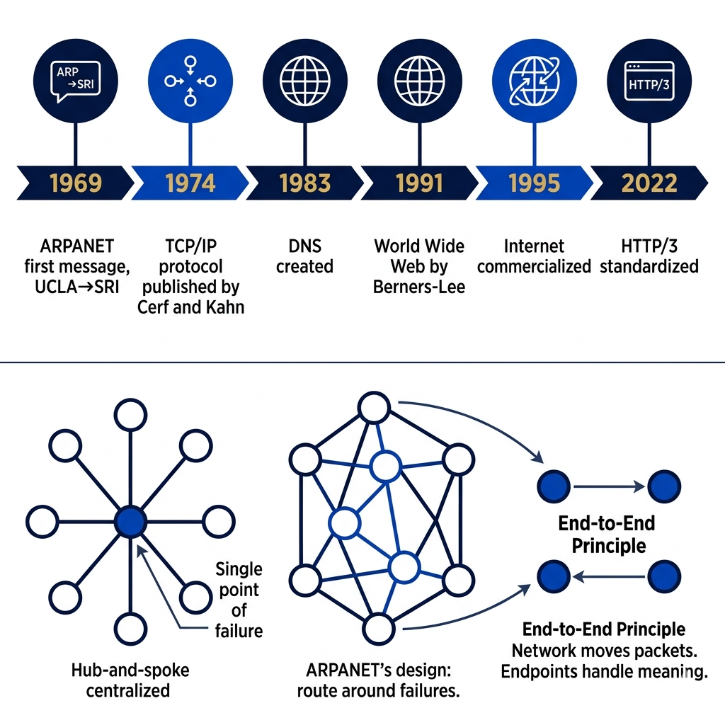
In the early 1960s, Paul Baran at RAND Corporation was working on a problem that sounds almost quaint by modern standards: how do you build a communications network that survives a nuclear attack? The existing telephone network was centralized — destroy the switching center, and you destroy communication for everyone connected to it. Baran's answer was distributed mesh networking: route messages through any available path, with no single point of failure. If one path is destroyed, traffic routes around it.
This concept — messages broken into small blocks, each routed independently through whatever path is available — became the theoretical foundation of packet switching, and eventually of ARPANET. The Defense Advanced Research Projects Agency (DARPA) funded the project, and in 1969, the first ARPANET message was sent from UCLA to the Stanford Research Institute. It was supposed to be "LOGIN." The system crashed after "LO." But the fact that anything arrived was the proof of concept that mattered.
The TCP/IP protocol suite, developed by Vint Cerf and Bob Kahn in the 1970s, was the moment ARPANET's architecture became the internet's architecture. Their key insight — the end-to-end principle — was that intelligence should be at the edges of the network (in the devices), not in the middle (in the infrastructure). The network's job is to move packets. The job of interpreting, ordering, and error-checking those packets belongs to the endpoints. This design decision is why the internet scales: adding a new application or a new type of device doesn't require changes to the core network. The internet doesn't know what HTTPS is, what streaming video is, or what a cryptocurrency transaction is — it just moves packets. The applications define their own meaning.
Tim Berners-Lee's invention of the World Wide Web in 1989–1991 was an application built on top of the internet — not the internet itself. This distinction matters more than it might seem. Email, FTP, DNS, and SSH all existed before the web. They run on the same internet infrastructure as HTTP. The web is one application layer protocol (HTTP) built on the internet's transport infrastructure. Understanding this layering is the foundation for understanding everything else in this post.
# Tracing the internet's history through its protocols
# DNS was invented in 1983 — before the web
dig +short google.com    # DNS query — the phonebook of the internet

# The web (HTTP) is just one application on top of the internet's infrastructure
# These all run on the same TCP/IP stack:
curl https://api.github.com          # HTTP/HTTPS — web
ssh user@server.com                  # SSH — secure shell
ftp ftp.example.com                  # FTP — file transfer
telnet towel.blinkenlights.nl        # Telnet — the protocol that predated SSH

# The end-to-end principle in action:
# The network (routers) just forward packets — they don't care about content
# Only endpoints (your computer, the server) interpret the data
# This is why the internet works for applications that didn't exist when it was designed

# Check what's connecting you to the internet right now:
ip route show       # Linux: your local routing table
netstat -rn         # macOS/Linux: routing table
route print         # Windows: routing table
# The "default" route (0.0.0.0/0) is your gateway — the first hop into the internet
Pro Tips & Common Mistakes — Internet History
Pro Tip: The end-to-end principle is the most important design concept in internet architecture and the most frequently violated in modern enterprise networks. Every time someone puts deep packet inspection, traffic shaping, or application-aware middleboxes in the network core, they're moving intelligence from the edge to the middle — the opposite of the design that made the internet scale. Understanding this principle helps you reason about why VPNs, NAT, and firewalls create the problems they do: they're all violations of the end-to-end assumption.
Common Mistake: Conflating "the internet" with "the web." The internet is infrastructure (physical cables, routers, protocols for moving packets). The web is an application built on that infrastructure (HTTP, HTML, URLs). When people say "the internet went down," they usually mean "my HTTP requests are failing" — which could be DNS, routing, TLS, or the web server, not necessarily the internet infrastructure itself. This distinction matters when debugging.
Network Edge and Access Networks: Where Devices Connect
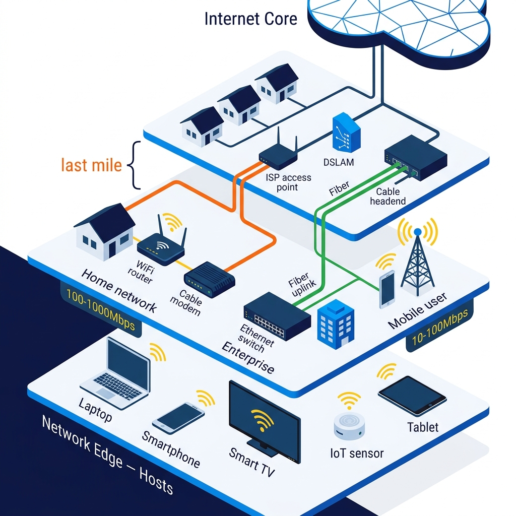
The network edge is where you live — every computer, phone, smart speaker, thermostat, and camera that connects to the internet. These devices are called hosts or end systems because they host applications and sit at the ends of the communication paths. They don't route traffic for others; they generate and consume it. The distinction between edge (hosts) and core (routers) is one of the internet's fundamental architectural choices, and it maps directly to the end-to-end principle from the previous section.
Getting from a host to the internet requires an access network — the local infrastructure that bridges your device to the global network. Home broadband (cable, DSL, or fiber) connects via a modem to your ISP's network. A cable modem shares bandwidth with your neighborhood using a shared medium architecture, which is why your speeds vary based on how many neighbors are streaming at the same time. Fiber connections are dedicated circuits — your fiber doesn't share physical infrastructure with your neighbor's fiber, which is why fiber latency is more consistent. Enterprise and institutional networks use Ethernet switching to aggregate many devices onto high-bandwidth uplinks to their ISP. Mobile access networks (4G LTE, 5G) connect devices over radio frequency, with base stations aggregating cellular traffic onto wired backhaul infrastructure.
The last mile — the connection between your home or office and the first major infrastructure point of your ISP — is often the bottleneck in end-to-end performance. Despite fiber links running at 100Gbps+ across continents, many users connect via copper telephone lines running ADSL at 10–50 Mbps, or cable systems shared among dozens of households. The asymmetry of most access connections (much faster download than upload) reflects a historical assumption about how most people use the internet — download more than upload — that has been increasingly challenged by video calls, cloud backups, and content creation.
Imagine the internet as a global highway system. The core network — intercontinental fiber, high-capacity backbone routers — is the freeway system: extremely high capacity, purpose-built for fast long-distance traffic. The access network is the local streets and neighborhood roads: lower capacity, serving the last stretch to individual destinations. Your broadband connection is the driveway from your house to the street. Performance problems are usually in the local roads and driveway, not on the freeway.
# Exploring your network edge and access connection

# Your device's network interfaces — the actual hardware connecting you
ip addr show              # Linux: all network interfaces
ifconfig                  # macOS: network interfaces
ipconfig /all             # Windows: detailed network information

# Key information to understand:
# inet 192.168.1.x — your private IP address (local network)
# inet6 fe80::... — your IPv6 link-local address
# ether xx:xx:xx:xx:xx:xx — your MAC address (hardware identifier)

# Your gateway — first hop out of your local network
ip route show default     # Linux
netstat -rn | grep default  # macOS

# The difference between your local IP and your public IP:
# Your local IP (192.168.x.x or 10.x.x.x) — assigned by your router, private
# Your public IP — assigned by your ISP, visible to the internet
curl ifconfig.me          # What the internet sees your IP as
# Usually different — that's NAT (Network Address Translation) at work

# Measure your actual access network performance:
# Download speed test via CLI:
curl -o /dev/null -s -w "%{speed_download}" https://speedtest.tele2.net/100MB.zip
# Latency to your ISP's gateway:
ping -c 10 $(ip route show default | awk '/default/ {print $3}')
# Packet loss and jitter (important for VoIP/video):
mtr --report --report-cycles 20 8.8.8.8

# Find where your home/office internet connects to the wider internet:
traceroute 8.8.8.8
# First 2-4 hops are your local network and ISP access equipment
# The hops after that are your ISP's backbone and peering points
Pro Tips & Common Mistakes — Network Edge
Pro Tip: Understanding the difference between private and public IP addresses is essential for debugging network issues. If your application works locally but not from external networks, the first question is: are you testing against a private IP (192.168.x.x, 10.x.x.x, 172.16–31.x.x) that's not reachable from the internet, or a public IP? NAT (Network Address Translation) is why most home and enterprise devices have private IPs — the router translates all internal devices' traffic to appear as a single public IP to the outside world.
Common Mistake: Assuming latency problems are in the cloud or on the server. In reality, the first two hops of any network path (your local network and your ISP's access equipment) are responsible for a surprisingly high percentage of latency variance. Running
mtr(a combined ping/traceroute tool) reveals whether latency is increasing near your local access point or further along the path. High latency at hop 1 or 2 indicates a local congestion problem, not a server problem.
Packet Switching: How Data Actually Travels
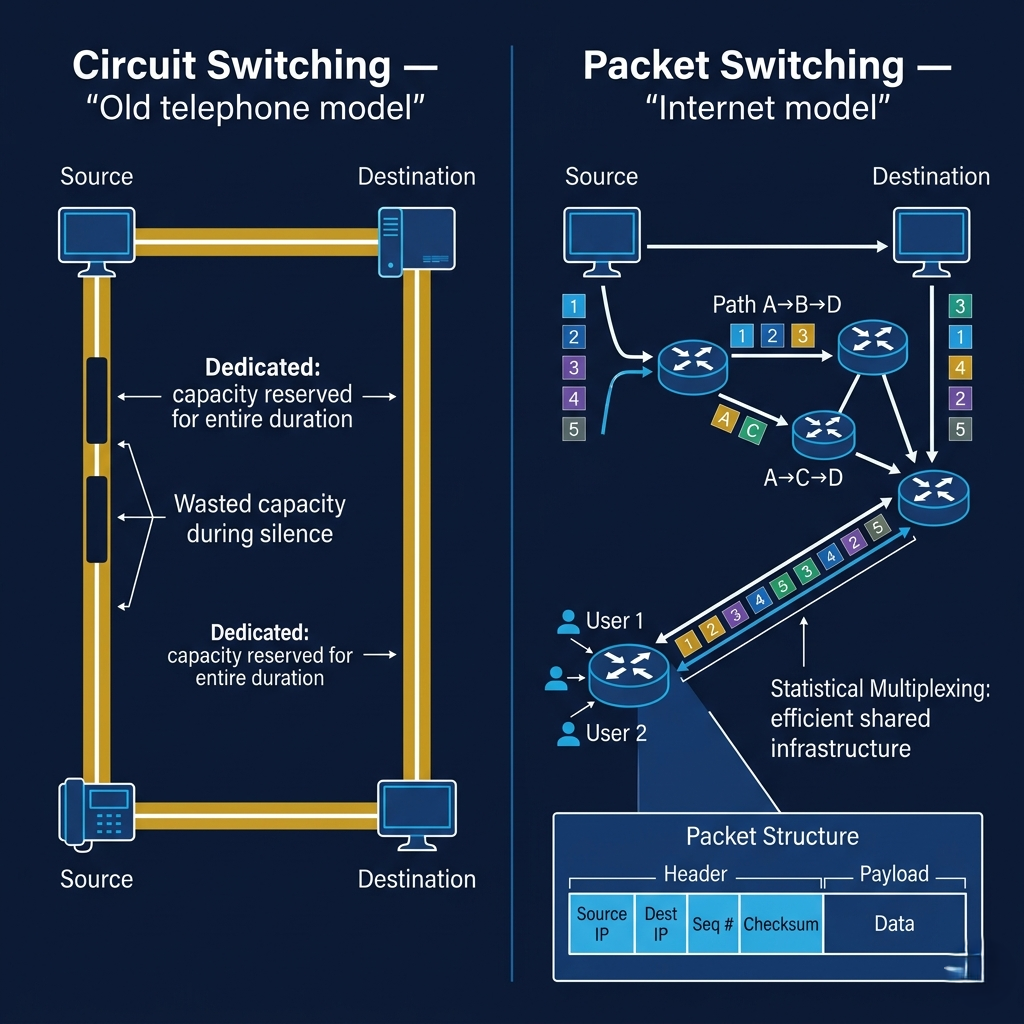
Before packet switching, the dominant communication paradigm was circuit switching — the model used by the telephone network. To make a phone call, the system establishes a dedicated physical circuit between caller and receiver. That circuit is reserved for the duration of the call, even during silence. If you're on a 10-minute call with 7 minutes of silence, the circuit is occupied for all 10 minutes regardless. Circuit switching guarantees capacity but wastes it massively.
Packet switching throws out this model entirely. Data is broken into discrete chunks called packets, each containing a small piece of the data (typically 1,500 bytes for Ethernet frames), a destination address, a source address, and sequence information. These packets are then routed independently through the network — they may take different paths, arrive out of order, or be delayed by congestion at intermediate routers. The destination device reassembles them into the original data in the correct order. The network doesn't reserve a path or guarantee capacity; it just moves packets on a best-effort basis.
The counterintuitive insight that makes packet switching work: statistical multiplexing. While a circuit-switched network needs to provision capacity for every simultaneous call at peak demand, a packet-switched network can oversubscribe capacity because not all users are transmitting at full rate simultaneously. A 10 Gbps link doesn't need to serve only 10 users at 1 Gbps each — it can serve thousands of users whose combined usage averages to 10 Gbps, because they're not all sending full-rate simultaneously. This is why the internet is economically viable at its scale: infrastructure is shared and resources are efficiently utilized rather than reserved.
Packet switching does introduce new problems that circuit switching doesn't have. Variable delay (jitter) occurs because packets may wait different amounts of time in router queues depending on network congestion. Packet loss occurs when router queues overflow and packets are dropped. Out-of-order delivery occurs because different packets may take different paths with different latencies. TCP's job — the T in TCP/IP — is to handle all of these realities transparently, providing the illusion of a reliable, ordered byte stream over an unreliable, unordered packet network.
# Simulating packet switching concepts in Python
import struct
import hashlib
from typing import List

MAX_PACKET_SIZE = 1400  # bytes (slightly under Ethernet MTU to avoid fragmentation)

def packetize(data: bytes, source_ip: str, dest_ip: str) -> List[dict]:
    """
    Break data into packets — simulating how packet switching works.
    Each packet gets its own header with addressing and sequence info.
    """
    packets = []
    total_chunks = (len(data) + MAX_PACKET_SIZE - 1) // MAX_PACKET_SIZE

    for seq_num, i in enumerate(range(0, len(data), MAX_PACKET_SIZE)):
        chunk = data[i:i + MAX_PACKET_SIZE]
        packet = {
            'source_ip': source_ip,
            'dest_ip': dest_ip,
            'sequence_number': seq_num,
            'total_packets': total_chunks,
            'payload': chunk,
            'payload_size': len(chunk),
            # Checksum for error detection (like IP header checksum)
            'checksum': hashlib.md5(chunk).hexdigest()[:8]
        }
        packets.append(packet)

    return packets

def reassemble(packets: List[dict]) -> bytes:
    """
    Reassemble packets into original data — like TCP's receiver buffer.
    Handles out-of-order delivery by sorting on sequence number.
    """
    # Sort by sequence number — packets may arrive out of order
    sorted_packets = sorted(packets, key=lambda p: p['sequence_number'])

    # Verify no gaps (detect packet loss)
    for i, packet in enumerate(sorted_packets):
        if packet['sequence_number'] != i:
            raise ValueError(f"Missing packet at sequence {i} — packet loss!")

        # Verify checksum (detect corruption)
        expected_checksum = hashlib.md5(packet['payload']).hexdigest()[:8]
        if packet['checksum'] != expected_checksum:
            raise ValueError(f"Corrupt packet at sequence {i}!")

    # Reassemble in order
    return b''.join(p['payload'] for p in sorted_packets)

# Demonstration
original_data = b"Hello, internet! " * 500  # 8500 bytes of data
print(f"Original data: {len(original_data)} bytes")

# Break into packets
packets = packetize(original_data, source_ip="192.168.1.10", dest_ip="93.184.216.34")
print(f"Packetized into: {len(packets)} packets of max {MAX_PACKET_SIZE} bytes each")

# Simulate network delivery (packets arrive out of order)
import random
shuffled = packets.copy()
random.shuffle(shuffled)
print(f"Packets arrived in order: {[p['sequence_number'] for p in shuffled[:5]]}... (shuffled)")

# Reassemble
reassembled = reassemble(shuffled)
assert reassembled == original_data, "Data corruption!"
print(f"Reassembled: {len(reassembled)} bytes — identical to original ✓")

# Key insight: the network delivered packets in any order
# The endpoint (this code, like TCP) handles reordering
# This is the end-to-end principle in code form
Pro Tips & Common Mistakes — Packet Switching
Pro Tip: The MTU (Maximum Transmission Unit) — the maximum packet size a network link will carry — is one of the most common sources of mysterious network issues. Ethernet's MTU is 1500 bytes. VPNs and tunneling protocols add headers, reducing the effective payload size. If your VPN connection drops large file transfers or video calls but handles small requests fine, MTU mismatch is the likely culprit. On Linux,
ip link show eth0shows the configured MTU;ping -M do -s 1472 google.comtests if large packets are getting through (1472 bytes + 28 bytes of headers = 1500 byte MTU).
Common Mistake: Treating packet loss as a binary "working/not working" condition. In reality, 0.1% packet loss is barely noticeable for most TCP traffic (TCP retransmits efficiently). 1% packet loss starts degrading video calls and gaming noticeably. 5%+ packet loss makes TCP throughput collapse due to congestion control backing off. Network monitoring should track packet loss as a continuous metric, not just connectivity. The
mtrtool shows per-hop packet loss across the path.
The Network Core: Routers, Forwarding, and Routing Algorithms
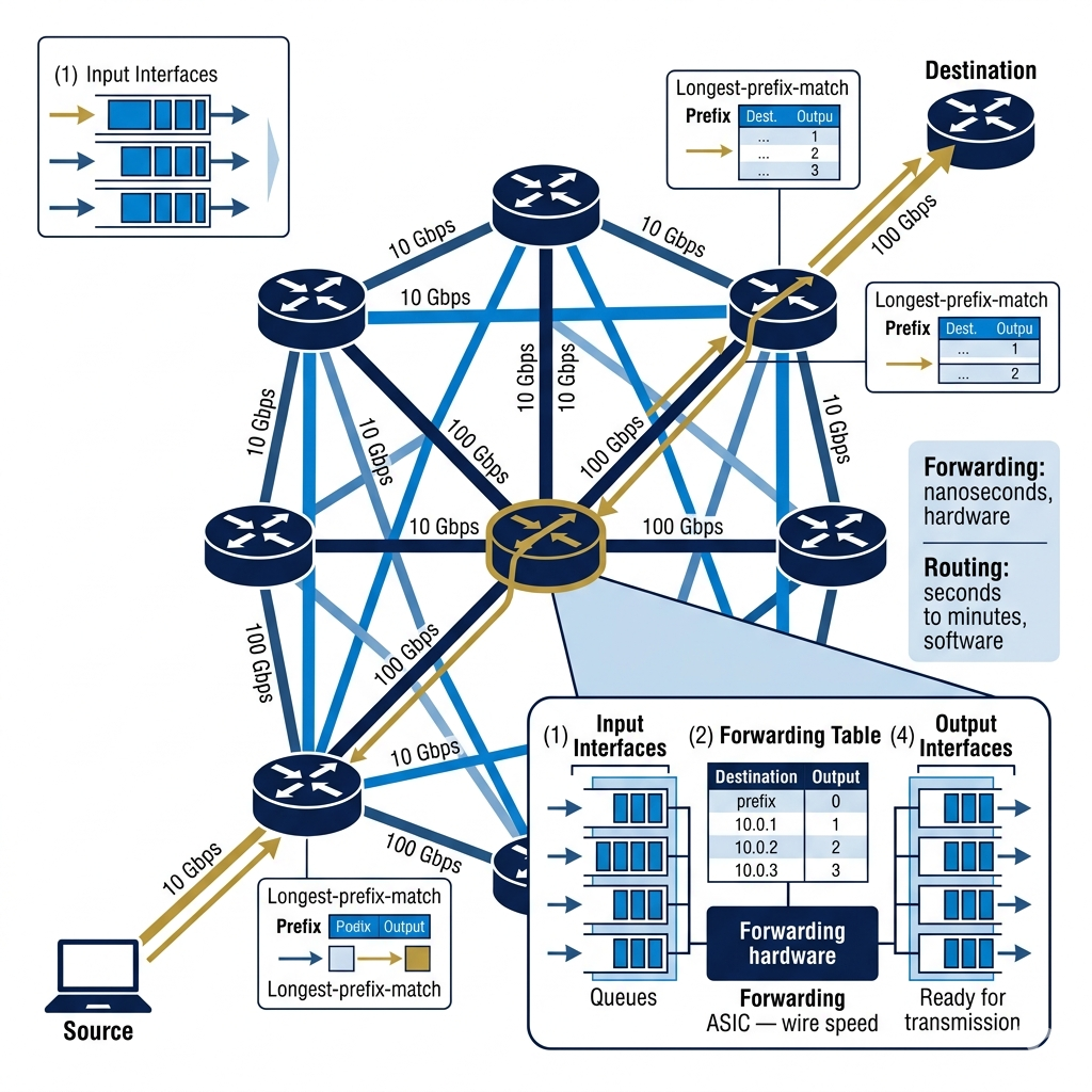
If the network edge is where data originates and terminates, the network core is where it travels. The core consists of routers — specialized devices whose sole purpose is to receive packets on one interface and forward them out another interface toward their destination. A router in the internet core might have dozens of interfaces, each connected to links running at 100 Gbps or higher, forwarding millions of packets per second, 24 hours a day, seven days a week, for years.
Routers perform two fundamentally different functions that are easy to conflate but important to distinguish. Forwarding is the local, fast operation: looking at a packet's destination IP address, checking the routing table (a data structure mapping destination address prefixes to output interfaces), and sending the packet out the correct interface. Forwarding happens in hardware for performance — modern line-rate forwarding uses custom ASICs (Application-Specific Integrated Circuits) that can process packets at wire speed without CPU involvement. Routing is the distributed, slow operation: building and maintaining the routing table by exchanging information with neighboring routers about what destinations are reachable via which paths. Routing runs as software on the router's control plane.
The routing table maps destination address prefixes (like 172.217.0.0/16 — Google's IP range) to next-hop routers and output interfaces. When a packet arrives, the router does a longest prefix match — finding the most specific entry in the routing table that matches the packet's destination. A packet destined for 172.217.12.34 matches both 172.217.0.0/16 (Google) and 0.0.0.0/0 (the default route), but the /16 match is longer (more specific), so the router uses it. This longest-prefix-match algorithm, running in hardware at nanosecond speed, is how billions of packets per second find their way across the internet.
Routing algorithms — the software that builds routing tables — come in two main flavors. Link-state routing (used by OSPF inside large networks) has every router broadcast its complete view of the network topology to all other routers. Each router independently runs Dijkstra's shortest path algorithm on the complete graph to compute optimal routes. It converges quickly but requires every router to maintain and process the entire network's topology. Distance-vector routing (used by older protocols like RIP) has each router share only its routing table (distances to destinations, not topology) with immediate neighbors. Routes propagate hop-by-hop. It's simpler but converges slowly and can suffer from routing loops.
# Exploring the network core from your terminal

# See your local routing table — the forwarding table on your own machine
# Your machine is the simplest possible "router": one inside interface, one outside
ip route show          # Linux
netstat -rn            # macOS/Linux
route print            # Windows

# Example output:
# default via 192.168.1.1 dev eth0   ← all unknown destinations → gateway
# 192.168.1.0/24 dev eth0            ← local network, send directly
# 10.0.0.0/8 via 10.8.0.1 dev tun0  ← VPN route

# Longest prefix match in action:
# Packet to 192.168.1.25:
#   Matches: 192.168.1.0/24 (specific) AND default/0 (general)
#   /24 wins — sent directly on eth0

# Packet to 8.8.8.8 (Google DNS):
#   Matches: default/0 only
#   Sent to gateway (192.168.1.1) for forwarding

# Traceroute: see every router hop between you and a destination
traceroute 8.8.8.8          # macOS/Linux
tracert 8.8.8.8             # Windows
# Each line = one router hop, with RTT measurements to that router

# Better traceroute with per-hop packet loss stats:
mtr --report-cycles 20 8.8.8.8

# Detailed router analysis:
# Time to first hop (your gateway): typically < 2ms
# Time to ISP backbone: typically 5-20ms
# Time across continent: 20-80ms
# Time transatlantic: 80-120ms
# These physics-limited times reflect actual fiber cable distances

# Check OSPF/BGP routing if you have access to a router:
# (Cisco IOS commands)
# show ip route          — forwarding table
# show ip ospf neighbor  — OSPF routing protocol neighbors
# show ip bgp summary    — BGP routing protocol peers
Pro Tips & Common Mistakes — Network Core
Pro Tip: When debugging latency issues between your application and a remote service, use
tracerouteormtrto identify which hop is introducing latency. Each hop represents a router in the path — the RTT increase between hops reveals where time is being added. Consistent high latency at a specific hop (say, 120ms) followed by similar RTT for remaining hops means the latency was introduced at that hop, not beyond it. Latency that grows steadily at each hop typically indicates a long-distance fiber link (transatlantic, intercontinental).
Common Mistake: Interpreting high RTT at an intermediate traceroute hop as a "problem" when downstream hops show lower RTT. Some routers deprioritize ICMP/UDP probes used by traceroute (the network management traffic used to generate traceroute responses) while forwarding actual data traffic normally. A hop showing 200ms RTT followed by a destination showing 20ms RTT doesn't mean the path goes backward — it means that router rate-limits its probe responses. Focus on the final destination RTT and on hops where RTT consistently increases.
BGP: The Protocol That Holds the Internet Together
The routing protocols inside a single network — OSPF inside a university network, for example — assume trust. Every router shares full topology information with every other router. This works within an organization, but it would be catastrophically unsafe between organizations: you wouldn't want to share your internal network topology with every ISP on the internet, and you wouldn't want every ISP's routing decisions to influence traffic flow inside your private network.
The internet is divided into Autonomous Systems (ASes) — independently administered networks, each with its own routing policies and infrastructure. Your home ISP is an AS. Google is an AS (actually several). Amazon Web Services is an AS. A university network is an AS. Each AS has an AS Number (ASN) — a globally unique identifier assigned by regional internet registries (ARIN in North America, RIPE in Europe, APNIC in Asia-Pacific). There are roughly 100,000 active ASes on the internet today.
BGP (Border Gateway Protocol) is the routing protocol that connects these autonomous systems — it's the protocol that decides how traffic flows between ISPs, between cloud providers, between content delivery networks. BGP is often called "the glue that holds the internet together," and that description is accurate but understates its importance. It is the protocol through which every major network on earth announces which IP address ranges it owns and how to reach them. Without BGP, the globally connected internet would immediately fragment into isolated islands.
BGP is a path-vector protocol: when a router announces a route to a destination, it includes the complete sequence of AS numbers that traffic must traverse to reach that destination. 74.125.0.0/16 via AS-GOOGLE tells neighboring ASes that Google's address range is reachable through Google's AS. When that announcement propagates to other ASes, each one prepends its own AS number: 74.125.0.0/16 via AS-COMCAST, AS-GOOGLE. Downstream routers can see the full AS path and use it to avoid routing loops (if their own AS appears in the path, they discard the announcement) and to make policy decisions (prefer shorter paths, prefer certain carriers, avoid certain geographies for compliance reasons).
Here's the thing most networking tutorials miss about BGP: it is fundamentally a policy protocol, not just a routing protocol. Unlike OSPF (which finds the shortest path), BGP finds the path that satisfies the policy preferences of everyone along the route. Routing decisions are based on business relationships: transit agreements (AS A pays AS B to carry traffic), peering agreements (AS A and AS B exchange traffic between their customers at no charge), and customer/provider relationships (small ISP pays large ISP for internet access). The internet's routing reflects its economics, not just its topology
# Exploring BGP and Autonomous Systems

# Find your own AS number:
# Your ISP operates an AS — you're a customer endpoint within it
curl -s https://ipinfo.io | python3 -m json.tool
# Look for "org" field: "AS15169 Google LLC" means you're on Google's network

# Look up any IP's ASN and routing information:
# Using the RIPE Routing Information Service:
curl -s https://stat.ripe.net/data/routing-status/data.json?resource=8.8.8.8 | \
  python3 -m json.tool | grep -A5 "origin"

# BGP looking glass — see actual BGP routing tables from major routers:
# Route Views project provides public BGP data access:
# telnet route-views.routeviews.org
# Then: show ip bgp 8.8.8.8

# Find the AS path from your location to a destination:
# BGP path tools online:
# https://bgp.he.net — Hurricane Electric BGP toolkit
# https://bgp.tools — BGP community tools
# https://stat.ripe.net — RIPE's routing analysis

# Check BGP prefix announcements for a network:
# What IP ranges does Google announce to the internet?
whois -h whois.radb.net AS15169 | grep route | head -20

# Visualize BGP routing with traceroute + ASN lookup:
mtr --aslookup --report 8.8.8.8
# Output shows AS number at each hop:
# 1. AS??? 192.168.1.1 (your gateway — private, no ASN)
# 2. AS7922  96.120.x.x (Comcast — your ISP)
# 3. AS7922  68.85.x.x (Comcast backbone)
# 4. AS15169 209.85.x.x (Google's AS — traffic handed off here)
# 5. AS15169 8.8.8.8 (destination)

# BGP hijacking — a famous failure mode:
# In 2008, Pakistan Telecom (AS17557) accidentally announced a more-specific
# route for YouTube's IP range (74.125.0.0/24 more specific than /16)
# BGP's longest-prefix-match meant global traffic preferred the specific route
# YouTube was globally unreachable for ~2 hours
# This illustrates: BGP trusts announcements by default — verification is an ongoing effort
# RPKI (Resource Public Key Infrastructure) was developed to cryptographically
# verify that AS X is actually authorized to announce prefix Y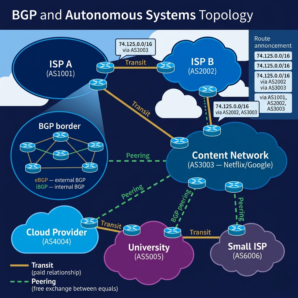
Pro Tips & Common Mistakes — BGP
Pro Tip: BGP route leaks and hijacks are real, ongoing security risks that can affect your application's availability even when your infrastructure is fully operational. In 2010, China Telecom accidentally announced routes for thousands of IP prefixes (including US military and government networks) through their BGP peers, briefly rerouting global internet traffic through China. Implementing RPKI (Resource Public Key Infrastructure) — route origin authorization that cryptographically proves an AS is authorized to announce specific prefixes — is the current best practice for mitigating hijacking. If you run infrastructure with BGP, check whether your upstream providers validate RPKI.
Common Mistake: Assuming your cloud provider or CDN routes traffic optimally just because they're large. BGP routing is based on policy and business relationships, not pure latency optimization. Traffic from your users to your AWS us-east-1 instance might route suboptimally based on peering relationships between your users' ISPs and AWS's network. Services like AWS Global Accelerator and Cloudflare's Argo use proprietary overlay networks that route over their own infrastructure rather than relying on BGP's best-effort routing — specifically because BGP optimizes for policy, not performance.
The TCP/IP Protocol Stack: Four Layers, One Internet
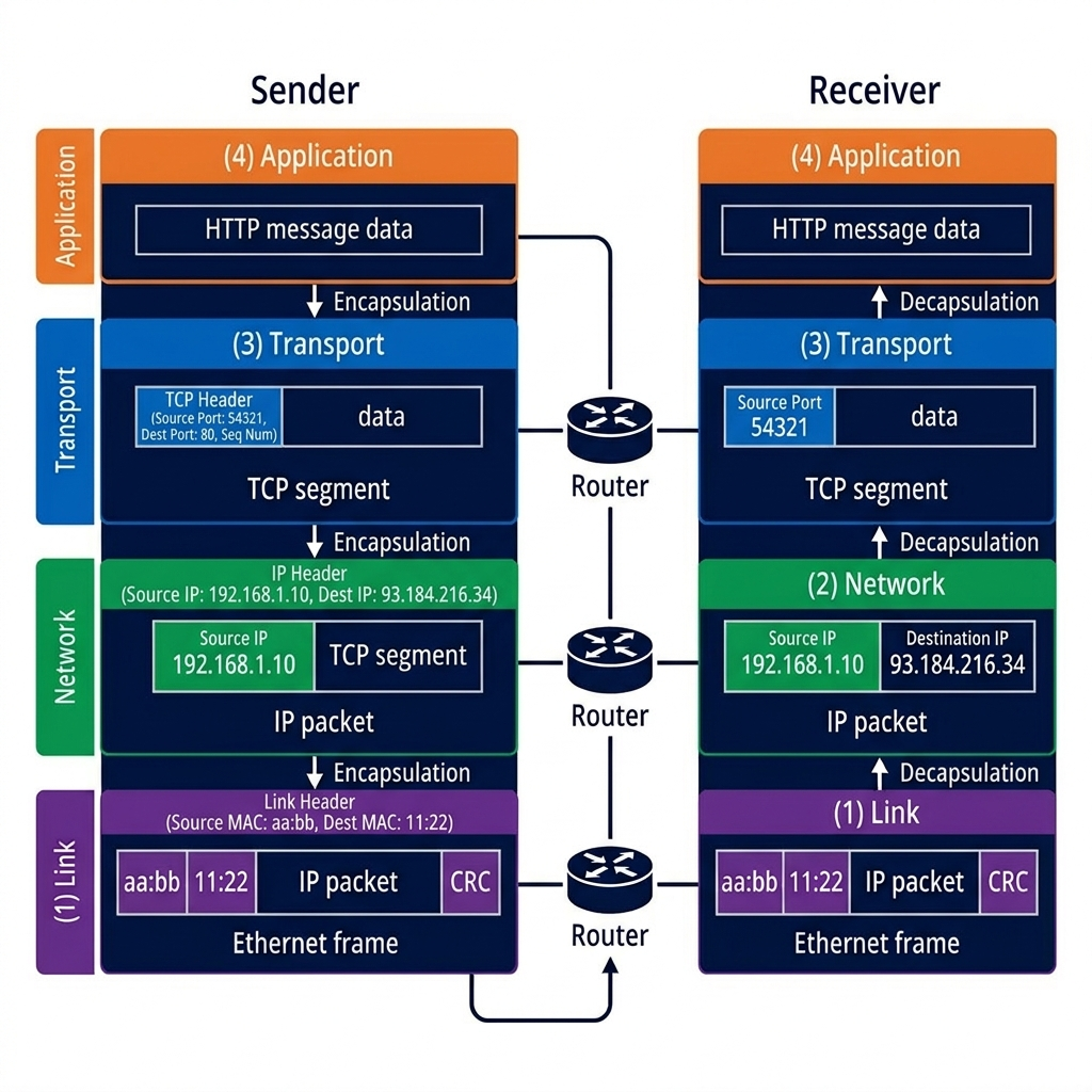
The internet's complexity is managed through layering — a principle borrowed from software engineering: each layer provides services to the layer above it and uses services from the layer below it, with clean interfaces between layers. The TCP/IP model has four layers, and every piece of data sent over the internet passes through all four of them — twice, once at the sender (going down the stack) and once at the receiver (going up the stack).
The Application Layer is where you live as a developer. HTTP, SMTP, DNS, SSH, FTP — these are all application layer protocols. They define the format and meaning of messages between applications: what a valid HTTP request looks like, what fields an email envelope contains, what a DNS query format is. The application layer doesn't know or care how its messages get from one machine to another; it hands them off to the transport layer and trusts that they'll arrive.
The Transport Layer (TCP and UDP) takes application layer messages and provides end-to-end communication services. TCP adds reliability (acknowledgments, retransmission), ordering (sequence numbers), and flow/congestion control on top of the unreliable packet network. UDP provides minimal services — just the addressing needed to deliver a datagram to the right application on the right machine. The transport layer abstracts the details of the network — whether you're on fiber, WiFi, or cellular — and presents a uniform interface to applications.
The Network Layer (IP) handles host-to-host routing across the internet. It assigns IP addresses, defines the packet format, and implements the forwarding and routing logic that moves packets from source to destination across multiple hops. IP is deliberately simple and unreliable — it delivers packets on a best-effort basis, with no guarantees of delivery, ordering, or maximum delay. This design allows the network layer to be efficiently implemented in hardware and to work across any underlying link technology.
The Link Layer handles communication on a single physical link — Ethernet, WiFi, fiber, cellular radio. It provides framing (packaging bits into frames), MAC addressing (physical hardware addresses used for local delivery), and error detection (CRC checksums). The link layer is technology-specific; IP runs on top of it and hides these details from higher layers. This is why IP can run over Ethernet, WiFi, cellular, satellite, and even 30-year-old fiber — the link layer adapts to the physical medium, and IP remains the same.
# Understanding protocol encapsulation — how data travels down and up the stack
# Each layer adds its own header (going down) and removes it (going up)

class ApplicationLayer:
    """HTTP request — what your application creates"""
    def create_http_request(self, method: str, path: str, host: str, body: str = "") -> bytes:
        request = f"{method} {path} HTTP/1.1\r\n"
        request += f"Host: {host}\r\n"
        request += f"Content-Length: {len(body)}\r\n"
        request += f"\r\n{body}"
        return request.encode()


class TransportLayer:
    """TCP segment — adds port numbers, sequence numbers, checksum"""
    def encapsulate(self, app_data: bytes, src_port: int, dst_port: int, seq_num: int) -> bytes:
        # Simplified TCP header (real TCP header = 20+ bytes)
        # Format: src_port(2) + dst_port(2) + seq_num(4) + flags(1) + data
        tcp_header = struct.pack('!HHIB',
            src_port,   # Source port: identifies sending application
            dst_port,   # Destination port: identifies receiving application (80=HTTP, 443=HTTPS)
            seq_num,    # Sequence number: enables ordering and loss detection
            0x02        # Flags: SYN=0x02, ACK=0x10, etc.
        )
        return tcp_header + app_data

    def decapsulate(self, tcp_segment: bytes) -> tuple:
        header = tcp_segment[:9]
        src_port, dst_port, seq_num, flags = struct.unpack('!HHIB', header)
        data = tcp_segment[9:]
        return (src_port, dst_port, seq_num, data)


class NetworkLayer:
    """IP packet — adds source and destination IP addresses"""
    def encapsulate(self, transport_data: bytes, src_ip: str, dst_ip: str, ttl: int = 64) -> bytes:
        # Simplified IP header — real IP header = 20 bytes minimum
        # src_ip and dst_ip determine routing across the internet
        ip_header = f"IP:{src_ip}->{dst_ip} TTL:{ttl} LEN:{len(transport_data)} | ".encode()
        return ip_header + transport_data

    def decapsulate(self, ip_packet: bytes) -> tuple:
        header_end = ip_packet.index(b' | ') + 3
        header = ip_packet[:header_end].decode()
        data = ip_packet[header_end:]
        return (header, data)


class LinkLayer:
    """Ethernet frame — adds MAC addresses for local delivery, CRC for error detection"""
    def encapsulate(self, network_data: bytes, src_mac: str, dst_mac: str) -> bytes:
        # Frame: src_mac + dst_mac + ethertype + payload + CRC
        frame_header = f"ETH:{src_mac}->{dst_mac} TYPE:0800 | ".encode()
        # Real Ethernet adds a 4-byte CRC32 checksum at the end
        import binascii
        frame = frame_header + network_data
        crc = struct.pack('!I', binascii.crc32(network_data) & 0xFFFFFFFF)
        return frame + crc

# Complete encapsulation example — data going DOWN the stack (sender side)
import struct

app = ApplicationLayer()
transport = TransportLayer()
network = NetworkLayer()
link = LinkLayer()

# Step 1: Application creates HTTP request
http_request = app.create_http_request("GET", "/", "example.com")
print(f"App layer: {len(http_request)} bytes")

# Step 2: Transport layer wraps in TCP segment (adds ports, sequence numbers)
tcp_segment = transport.encapsulate(http_request, src_port=54321, dst_port=80, seq_num=1000)
print(f"Transport layer: {len(tcp_segment)} bytes (added TCP header)")

# Step 3: Network layer wraps in IP packet (adds IP addresses for routing)
ip_packet = network.encapsulate(tcp_segment, src_ip="192.168.1.10", dst_ip="93.184.216.34")
print(f"Network layer: {len(ip_packet)} bytes (added IP header)")

# Step 4: Link layer wraps in Ethernet frame (adds MAC addresses for local delivery)
eth_frame = link.encapsulate(ip_packet, src_mac="aa:bb:cc:dd:ee:ff", dst_mac="11:22:33:44:55:66")
print(f"Link layer: {len(eth_frame)} bytes (added Ethernet header + CRC)")

# At each router hop: Link layer stripped and replaced (MAC addresses are local to each hop)
# IP header decremented TTL (Time-To-Live) — prevents infinite routing loops
# TCP and Application headers unchanged until final destination

print("\nEncapsulation summary — what's inside what:")
print("[ Ethernet Frame [ IP Packet [ TCP Segment [ HTTP Request ] ] ] ]")
print("  ^Link layer       ^Network    ^Transport    ^Application")
print("  (local delivery)  (routing)   (reliability) (meaning)")
Pro Tips & Common Mistakes — Protocol Stack
Pro Tip: The TTL (Time-To-Live) field in the IP header is decremented by 1 at each router hop. When it reaches 0, the router discards the packet and sends an ICMP "Time Exceeded" message back to the source. This prevents packets from circulating forever due to routing loops. It's also exactly how
tracerouteworks: it sends packets with TTL=1 (triggers ICMP from first router), then TTL=2 (second router), and so on — building a map of the path by collecting each router's ICMP response. TTL in HTTP cache-control headers is a different, unrelated concept that borrows the name.
Common Mistake: Thinking the MAC address in an Ethernet frame identifies the packet's final destination. MAC addresses are link-local — they only have meaning on the local physical network segment (your home network, a datacenter rack). At each router hop, the Ethernet frame is stripped, the router reads the IP destination, updates the TTL, and creates a new Ethernet frame addressed to the next router's MAC address. The original source and destination IP addresses remain unchanged for the entire journey; the MAC addresses change at every single hop.
How It All Connects: Following a Packet Across the Internet
Let's trace a single HTTPS request from your laptop to a server in another country, watching every layer and every system we've discussed activate in sequence.
You type https://example.com in your browser. The browser needs the server's IP address, so it sends a DNS query — itself a UDP packet at the transport layer, an IP packet at the network layer, an Ethernet frame to your router at the link layer. The DNS response comes back with 93.184.216.34. This first exchange already traversed multiple AS boundaries via BGP-maintained routing tables.
Your browser initiates a TCP connection to 93.184.216.34:443. The SYN packet travels from your laptop, down through your access network (WiFi frame to router, Ethernet to your ISP, fiber to their backbone), into the network core. At each router, the link-layer frame is stripped, the IP header is read for destination address, a longest-prefix-match lookup finds the output interface, TTL is decremented, and a new link-layer frame is sent. BGP-populated routing tables guide the packet across AS boundaries — from your ISP's AS to a transit provider's AS to the AS hosting example.com's servers. Somewhere between 10 and 30 router hops later, your SYN arrives.
The TLS handshake follows over the TCP connection — the application layer's security ceremony that establishes an encrypted channel. Then your HTTP GET request is sent, encrypted, as application layer data, wrapped in a TCP segment (with sequence numbers for ordering and reliability), wrapped in an IP packet (with source and destination addresses for routing), wrapped in an Ethernet frame (with the current hop's MAC addresses for local delivery). The server sends back an HTTP response through the same layered process in reverse.
Every layer you've learned about activates for every single request, invisibly, in milliseconds. The history that led to packet switching explains why packets exist. The access network explains the first and last hops. BGP explains how the packet traverses autonomous systems. The protocol stack explains why every router only cares about layer 3 while your application cares only about layer 7. These systems don't just coexist — each layer exists specifically to serve the one above it.
Getting Started: Tools for Exploring the Internet's Architecture
Here's a practical toolkit for experiencing the internet's architecture firsthand — these commands turn abstract concepts into observable reality.
Step 1: Explore your network edge
# See your network interfaces and local IP
ip addr show             # Linux
ifconfig                 # macOS

# Find your public IP (what the internet sees)
curl ifconfig.me

# Check your default gateway (first hop into the internet)
ip route show default    # Linux
netstat -rn | grep ^default  # macOS
Step 2: Explore packet routing with traceroute
# Trace the route to a remote destination
traceroute 8.8.8.8            # Linux/macOS
tracert 8.8.8.8               # Windows

# Better: mtr shows ongoing statistics including packet loss
sudo apt install mtr -y       # Linux
brew install mtr              # macOS
mtr --aslookup 8.8.8.8        # Show ASN at each hop

# Interpret the output:
# First 1-3 hops: your local network and ISP access equipment
# Jump to 50-80ms: you're crossing an ocean (transatlantic/transpacific fiber)
# * * *: router not responding to probes (common, not a problem)
Step 3: Explore DNS and BGP
# DNS resolution — watch how a domain name becomes an IP
dig example.com A          # A record (IPv4 address)
dig example.com AAAA       # AAAA record (IPv6 address)
dig +trace example.com     # Full recursive resolution from root servers

# Find the ASN for any IP address
curl -s https://ipinfo.io/8.8.8.8 | python3 -m json.tool
# Look for "org": "AS15169 Google LLC"

# BGP looking glass — see actual internet routing tables
# Free public BGP data from Route Views project:
telnet route-views.routeviews.org
# At the prompt: show ip bgp 8.8.8.8
# Press Ctrl+C then type 'logout' to exit
Step 4: Explore the protocol stack with Wireshark
# Install Wireshark for visual packet capture
# macOS: brew install --cask wireshark
# Linux: sudo apt install wireshark

# Capture packets on your main interface
sudo tcpdump -i eth0 -n host 8.8.8.8    # Capture traffic to/from Google DNS

# While capturing, run: ping 8.8.8.8
# tcpdump shows each packet with:
# - Timestamp
# - Source IP → Destination IP
# - Protocol (ICMP, TCP, UDP)
# - Packet contents

# In Wireshark GUI, you can click any packet and see:
# - Ethernet frame (Link layer)
# - IP packet (Network layer)
# - TCP segment or UDP datagram (Transport layer)
# - Application data (HTTP, DNS, TLS, etc.)
# This is protocol stack decapsulation made visual

# Capture a complete HTTP exchange (no encryption):
sudo tcpdump -i eth0 -A -s 0 port 80 host example.com
curl http://example.com    # In another terminal
# tcpdump shows the raw HTTP request and response text
Step 5: Explore your routing table
# See all routes on your machine
ip route show                    # Linux (full routing table)
ip route get 8.8.8.8            # Linux: which route handles this destination?

# Add a static route (temporary, educational):
# sudo ip route add 10.0.0.0/8 via 192.168.1.1
# This routes all 10.x.x.x traffic through your gateway

# See all active connections (TCP state machine in action):
ss -tnp           # Linux: established TCP connections
netstat -an       # Cross-platform: all connections and their states
# States: ESTABLISHED (active), TIME_WAIT (closing), LISTEN (waiting for connections)
FAQ
Q: What is the internet and how is it different from the World Wide Web?
The internet is a global network of networks — physical infrastructure (cables, routers, switches) and protocols (TCP/IP) that connect billions of devices worldwide and enable data exchange between them. The World Wide Web is one application built on top of the internet, using HTTP as its application layer protocol and HTML for content. Email, SSH, DNS, FTP, and video calls are also applications that run on the internet but are not the web. When people say "the internet is down," they usually mean "I can't access websites via HTTP/HTTPS" — which might be a web server issue, not an internet infrastructure failure.
Q: What is packet switching and why does the internet use it instead of circuit switching?
Packet switching breaks data into small packets that travel independently through the network, potentially taking different paths and arriving out of order. Circuit switching (used by traditional phone networks) establishes a dedicated end-to-end path for an entire communication session. The internet uses packet switching because it enables statistical multiplexing — sharing infrastructure efficiently among many simultaneous users without reserving dedicated capacity for each. Circuit switching wastes capacity during idle periods; packet switching utilizes whatever capacity is available. The tradeoff is variable latency and the need for TCP to handle reordering and retransmission.
Q: What is an IP address and why do we need both IPv4 and IPv6?
An IP address is a numerical label assigned to each device on a network, used to identify and locate it for routing purposes. IPv4 uses 32-bit addresses (e.g., 192.168.1.1), providing approximately 4.3 billion unique addresses — a number that was unimaginably large in the 1970s but has been exhausted by the explosion of internet-connected devices. IPv6 uses 128-bit addresses (e.g., 2001:db8::1), providing 340 undecillion unique addresses — enough that every atom on earth could have its own IP address. NAT (Network Address Translation) has extended IPv4's lifespan by allowing many devices to share a single public IP, but IPv6 deployment is necessary for the long-term growth of internet-connected devices.
Q: What is BGP and why is it called the "glue of the internet"?
BGP (Border Gateway Protocol) is the routing protocol that enables different autonomous systems — independently administered networks like ISPs, cloud providers, and universities — to exchange routing information. Each AS announces which IP address ranges it owns and maintains; BGP propagates these announcements globally so every router knows how to reach every network. Without BGP, the internet would fragment into isolated networks with no way to route between them. BGP is called the internet's glue because it's the only mechanism that connects these independently operated networks into a coherent global system.
Q: What does the TCP/IP protocol stack do and why does it have four layers?
The TCP/IP stack has four layers, each handling a different aspect of network communication. The Application layer (HTTP, DNS, SMTP) defines message formats and meaning. The Transport layer (TCP, UDP) handles end-to-end reliability and port-based addressing. The Network layer (IP) routes packets across multiple hops using IP addresses. The Link layer (Ethernet, WiFi) handles single-hop physical delivery using MAC addresses. The layered design means each layer can change independently — the Application layer doesn't need to know about fiber versus WiFi (Link layer handles that), and adding a new application doesn't require changing routing protocols (Network layer handles that). Layers communicate through well-defined interfaces, enabling the modularity that makes the internet composable.
Q: What is the difference between a router and a switch?
A switch operates at the Link layer (Layer 2) and forwards Ethernet frames based on MAC addresses within a local network. It builds a MAC address table by observing which MAC addresses appear on which ports, then forwards frames only to the correct port. A router operates at the Network layer (Layer 3) and forwards IP packets based on IP addresses across different networks. Routers separate networks, perform NAT, maintain routing tables, and participate in routing protocols. In a typical home setup, the device labeled "router" is actually a router + switch + WiFi access point combined, but conceptually they're distinct functions.
Q: What is a DNS and how does it work?
DNS (Domain Name System) is the internet's distributed phonebook — it translates human-readable domain names (example.com) into IP addresses (93.184.216.34) that computers use for routing. A DNS lookup is a hierarchical query process: your browser first checks its local cache, then asks your operating system's resolver, which asks your configured DNS server (usually your ISP's or a public resolver like 8.8.8.8). If the answer isn't cached, the resolver queries root nameservers → TLD nameservers (.com, .org) → authoritative nameservers for the specific domain, in a process called recursive resolution. DNS runs over UDP (fast, simple lookups) with TCP fallback for large responses.
Q: What happens when you type a URL into a browser?
The sequence involves nearly every internet system discussed in this post. First, DNS resolves the domain to an IP address. Then your browser opens a TCP connection to the IP on port 80 (HTTP) or 443 (HTTPS), which requires a three-way handshake traveling through your access network, across multiple router hops via BGP-maintained routing tables, to the destination server. For HTTPS, a TLS handshake follows to establish encryption. Then the browser sends an HTTP request (Application layer) wrapped in a TCP segment (Transport layer) wrapped in an IP packet (Network layer) wrapped in an Ethernet frame (Link layer). The server receives it, processes it layer by layer up the stack, and sends back an HTTP response through the same process in reverse. Modern browsers parallelize multiple such requests simultaneously via HTTP/2 or HTTP/3 multiplexing.
Conclusion
The internet that handles 15 billion devices today uses the same fundamental architecture as ARPANET's 4-node network in 1969. Not because no one thought to improve it, but because the foundational decisions — packet switching, the end-to-end principle, the layered protocol stack, autonomous systems with BGP for inter-network routing — were correct at the architectural level. They've been extended, scaled, patched, and supplemented, but the core design has proven durable across six orders of magnitude of growth.
Understanding this architecture changes how you work as an engineer. When a distributed system has mysterious latency spikes, you know to look at the traceroute before the application logs. When a cloud service fails, you know whether the problem is DNS, routing, TLS, or application layer. When someone says "add BGP anycast," you know what routing announcement that entails. When you're debugging why a packet isn't arriving, you know which layer to look at — link layer for local delivery, network layer for routing, transport layer for reliability, application layer for meaning.
The internet's architecture is not just interesting history. It's the foundation that every distributed system runs on, and understanding it is the difference between treating the network as magic and treating it as a system you can reason about, observe, and debug.